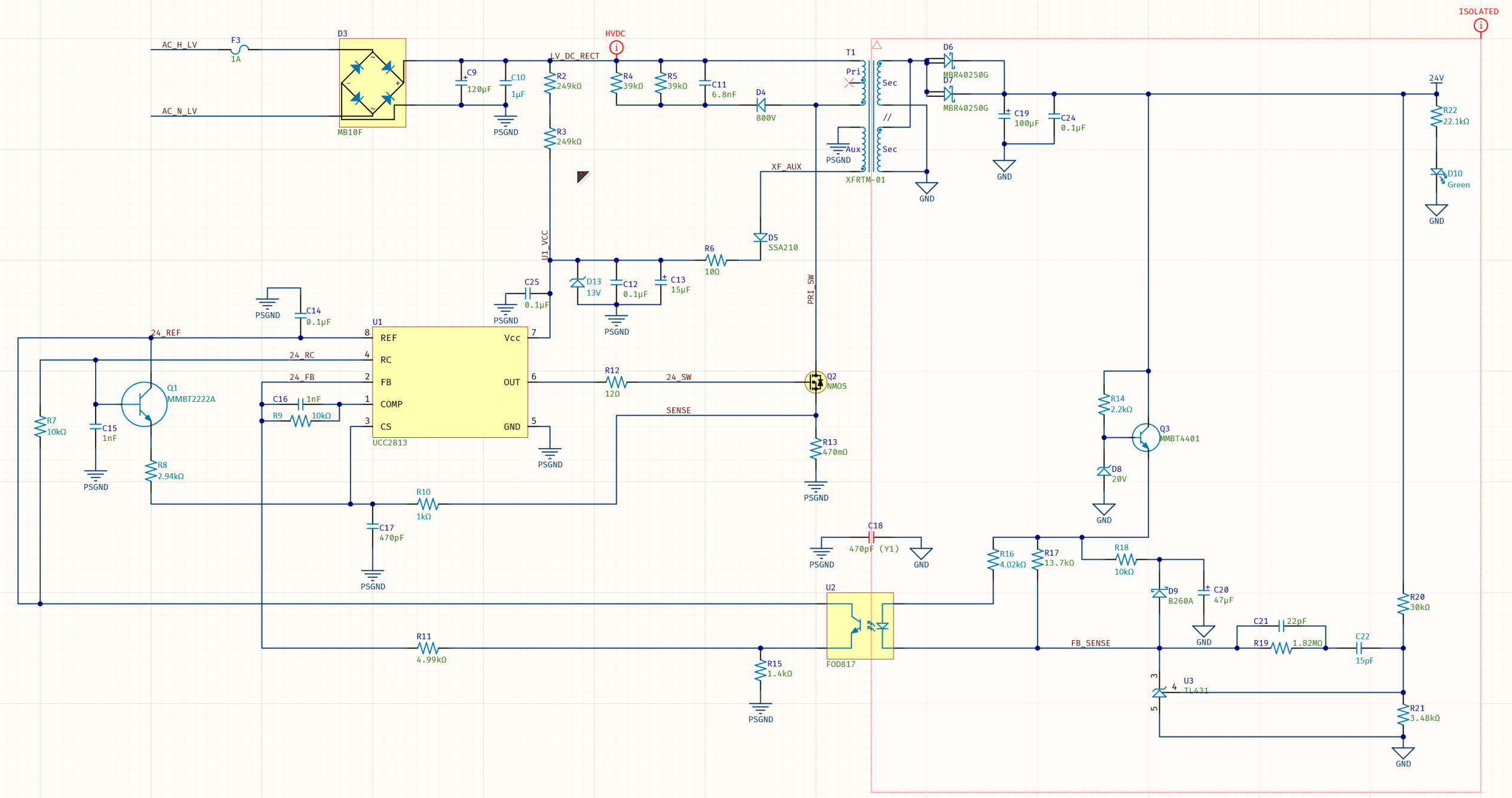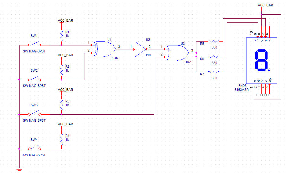
If you accepted the default directories during installation, the path should be similar to \Public Documents\Altium\AD14\Library\. Set the scope to Libraries on Path and make sure that the Path field contains the correct path to your libraries.This will open the Libraries Search dialog. Press the Search button in the Libraries panel, or select Tools » Find Component.Click on the Libraries tab to display the Libraries workspace panel.Locating Components and Loading Librariesįirst, we will search for the op amp component, LF411CN. In this section of the tutorial, we will locate the components required, set up their component properties and then wire the schematic. Before we can run a simulation, the schematic must contain components with SIM models attached, voltage sources to power the filter, an excitation source, a ground reference for the simulations and some net labels on the points of the circuit where we wish to view waveforms. Now we can create the Filter circuit shown below. Navigate to a location where you would like to store the schematic on your hard disk, type the name Filter.SchDoc in the File Name field and click on Save. SchDoc extension) by selecting File » Save As. Rename the new schematic file (with a.A blank schematic sheet named Sheet1.SchDoc displays in the design window of the Schematic Editor and the schematic sheet is now listed under Source Documents beneath the project name in the Projects panel.

Creating a New Schematic SheetĬreate a new schematic sheet by completing the following steps:
VCC IN PSPICE SCHEMATICS DOWNLOAD
If you do not have the time to draw the schematic from scratch, you can download a similar project Filter.PrjPCB from the Download Examples and Reference Designs page. This schematic will be for a Filter circuit. Next, we will create a new schematic sheet to add to the empty project file.

Navigate to a suitable location, type the name Filter.PrjPCB in the File Name field, and click on Save.

Please ignore the values of the resistors as I have input them because thats what I got after calculating R1 and R2. I have added very simplified schematics of overall system for better understanding.
VCC IN PSPICE SCHEMATICS SERIES
P.S: Vin is connected to a resistor (of value 1ohm in series with my 235V load) and Vout is connected to my microcontrollers ADC.

Again its my gut feeling which is not logical. What is the acceptable range of values for all the resistors in the circuit above?įrom my research I understood that R3 shouldn't be too big as its to protect the LED inside the optoisolator so should it be 20? 50? 100? 200? 300?įor R1 and R2 I got the feeling that minimum should be 10k. Where K3 is trasnfer gain of I元00 = K2/K1 So in order to get a linear relation between Vo and Vin, R2=R1 which makes From the datasheet, I am using circuit configuration as given in the datasheet: Typical Application Circuit Hi I am building a voltage sensor using Optoisolator/Optocoupler.


 0 kommentar(er)
